

I recently spotted a nice little compact development board for the PIC12F675, since this was a PIC that I hadn’t looked at I decided to buy one. This is the board I bought

About the board
External reset button.
Two user-programmable buttons which are connected to the microcontroller GP2 and GP5 pins and can be used as ordinary buttons use, or can be used as an external interrupt button.
A power indicator, two user-programmable LED
A pot connected
External 5V DC power connector – board comes with a USB to power connector
Power switch.
ICSP programming interface
If you remove the jumpers from the connectors you can use the I/O pins for your own purposes
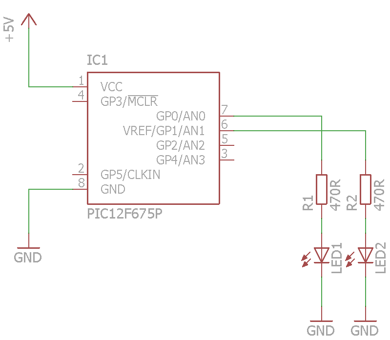
Schematic
I dont have a schematic for the board but I drew this one represents the 2 LEDs
Code
The code is written in mikroC pro for Pic
If you set a bit in the TRISIO register to zero this sets the pin direction to an output. In the following example we set all of the bits to zero. Now you can toggle the GPIO bits in various ways, in our example we send 0x02 which will toggle GP0 and GP1 high.
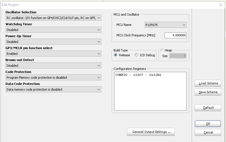
You need to configure your PIC12F675 to use the internal oscillator in the mikroC ide, to do this go to Project -> Edit Project, these are the settings
[codesyntax lang=”cpp”]
void main() {

  TRISIO = 0;

   while(1) { // infinite loop

      GPIO = 0x00;
      delay_ms(1000);

      GPIO = 0x03;
      delay_ms(1000);
  }
}
[/codesyntax]
Links
The board cost less than $7
PIC12F675 5V Development Board Learning Board Breadboard
