
RKPK40 Prototype PCB
The next PIC development board is again from RKeducation and is designed fo use with 40 pin PICs. In this case I used a PIC18f4550
Here are the specs for the 18f4550 – more details available at http://www.microchip.com/wwwproducts/Devices.aspx?product=PIC18F4550
| Parameter Name | Value |
| Program Memory Type | Flash |
| Program Memory (KB) | 32 |
| CPU Speed (MIPS) | 12 |
| RAM Bytes | 2,048 |
| Data EEPROM (bytes) | 256 |
| Digital Communication Peripherals | 1-UART, 1-A/E/USART, 1-SPI, 1-I2C1-MSSP(SPI/I2C) |
| Capture/Compare/PWM Peripherals | 1 CCP, 1 ECCP |
| Timers | 1 x 8-bit, 3 x 16-bit |
| ADC | 13 ch, 10-bit |
| Comparators | 2 |
| USB (ch, speed, compliance) | 1, FS Device, USB 2.0 |
| Temperature Range (C) | -40 to 85 |
| Operating Voltage Range (V) | 2 to 5.5 |
| Pin Count | 40 |
Here is a picture of the board in question
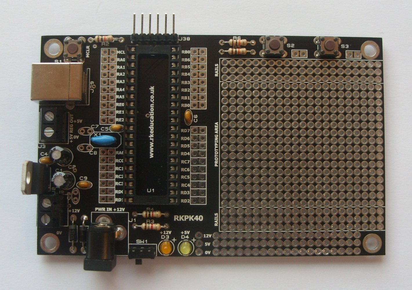
RKPK40
Features
Low cost development board at £7.99
Supports several PICs
Can be used with the Pickit programmers – tested with Pickit3
Prototyping area on board
5v regulator on board
Through hole components
USB connection can be used to power the board
The build is again fairly straightforward and only requires basic soldering skills.
I connected a Pickit3 to the programming header and verified if I could read the device connected. You can see this in the screenshot below.
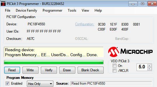
pickit pic18f4550
An easy way of testing is to connect some LEDs to one of the ports and flash them on and off. Here is a schematic with 3 LEDs displayed
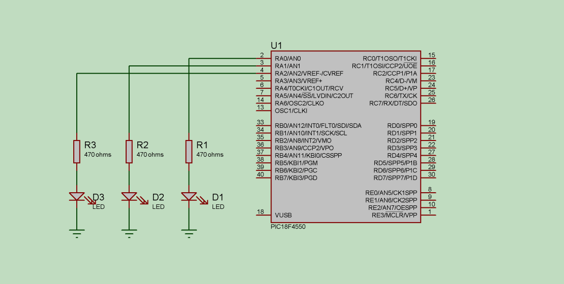
pic18f4550 and leds
Code
Simple example using MikroC for PIC
[codesyntax lang=”cpp”]
int main(void)
{
TRISA = 0x00; // Configure port A as output

while(1)
{
PORTA = 0x00;
delay_ms(1000); // Wait for 1s
PORTA = 0xFF;
delay_ms(1000); // Wait for 1s
}
}
[/codesyntax]
Links
