
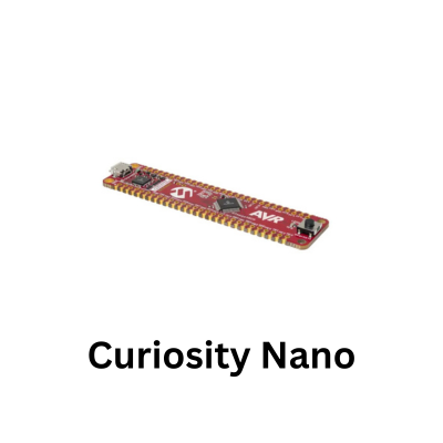
The curiosity nano explorer has 2 MCP23008 I/O expanders, both with unique addresses. There also 8 LEDs connected to the outputs of each expander. So lets see this
Introduction
The MCP23008 provides a straightforward way to expand the number of digital outputs available to a PIC18F56Q71 without consuming another eight microcontroller GPIO pins. In this project, the PIC18F56Q71 Curiosity Nano communicates with the MCP23008 over I2C and uses the expander’s GPIO outputs to control LEDs.
The examples can begin with switching a single LED on and off before progressing to several LEDs, allowing different output patterns to be generated by writing new values to the MCP23008.
This makes the visible LED activity a useful confirmation that both the I2C communication and GPIO-expander configuration are working correctly.
Controlling several LEDs also demonstrates one of the main advantages of a port expander: an entire group of external outputs can be represented by a single byte and updated through the MCP23008’s registers.
Individual bits can control individual LEDs, while complete byte values can produce binary counters, running-light sequences and other patterns without requiring eight dedicated PIC18F56Q71 output pins.
The experiment therefore provides a useful introduction to register-oriented I2C devices, where the microcontroller first selects how the MCP23008 pins should operate and then reads or modifies its internal registers to control the external hardware.
The same approach can later be extended to switches, relays, indicators and other low-current digital signals when additional GPIO is required.
Image
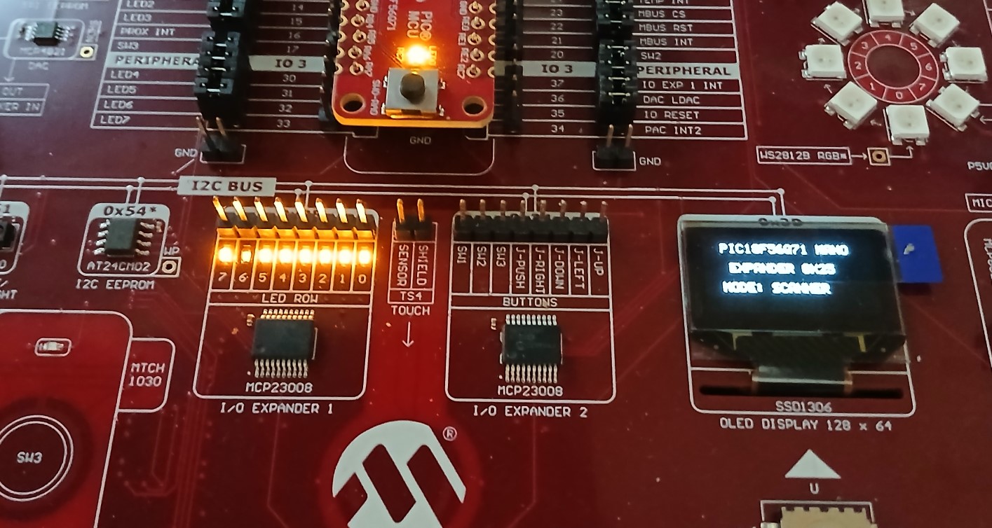
- MCP23008 LED and OLED
Code
To create an LED lighting sequence:
-
Write 0x00 to the IODIR register (0x00) to set all 8 pins (GP0–GP7) as digital outputs.
-
Send bitmask bytes to the GPIO register (0x09) to control the output states.
The complete standalone program below drives a 4-mode animation loop across GP0–GP7 (Knight Rider scanner, expanding bar, binary counter, and alternating flash) while outputting the current mode status to the SSD1306 OLED display.
// Configuration Bits for PIC18F56Q71
#pragma config FEXTOSC = OFF
#pragma config RSTOSC  = HFINTOSC_1MHZ // Software switches to 16MHz
#pragma config CLKOUTEN = OFF
#pragma config CSWEN   = ON
#pragma config MCLRE   = EXTMCLR
#pragma config PWRTS   = PWRT_OFF
#pragma config WDTE    = OFF

#define _XTAL_FREQ 16000000
#include <xc.h>

// I2C Addresses on Explorer Board
#define SSD1306_I2C_ADDR   0x3D
#define EXPANDER_I2C_ADDR  0x25

// MCP23008 Registers
#define MCP23008_REG_IODIR 0x00  // I/O Direction Register (0 = Output, 1 = Input)
#define MCP23008_REG_GPIO  0x09  // General Purpose I/O Port Register

#define HEARTBEAT_LED      LATCbits.LATC7

// Software I2C Pin Definitions (RC3 = SCL, RC4 = SDA)
#define SCL_PIN TRISCbits.TRISC3
#define SDA_PIN TRISCbits.TRISC4
#define SDA_IN  PORTCbits.RC4

// Font Table (ASCII 32 to 90)
const unsigned char FONT_5x7[][5] = {
    {0x00, 0x00, 0x00, 0x00, 0x00}, // ' '
    {0x00, 0x00, 0x5F, 0x00, 0x00}, // '!'
    {0x00, 0x07, 0x00, 0x07, 0x00}, // '"'
    {0x14, 0x7F, 0x14, 0x7F, 0x14}, // '#'
    {0x24, 0x2A, 0x7F, 0x2A, 0x12}, // '$'
    {0x23, 0x13, 0x08, 0x64, 0x62}, // '%'
    {0x36, 0x49, 0x55, 0x22, 0x50}, // '&'
    {0x00, 0x05, 0x03, 0x00, 0x00}, // '\''
    {0x00, 0x1C, 0x22, 0x41, 0x00}, // '('
    {0x00, 0x41, 0x22, 0x1C, 0x00}, // ')'
    {0x14, 0x08, 0x3E, 0x08, 0x14}, // '*'
    {0x08, 0x08, 0x3E, 0x08, 0x08}, // '+'
    {0x00, 0x50, 0x30, 0x00, 0x00}, // ','
    {0x08, 0x08, 0x08, 0x08, 0x08}, // '-'
    {0x00, 0x60, 0x60, 0x00, 0x00}, // '.'
    {0x20, 0x10, 0x08, 0x04, 0x02}, // '/'
    {0x3E, 0x51, 0x49, 0x45, 0x3E}, // '0'
    {0x00, 0x42, 0x7F, 0x40, 0x00}, // '1'
    {0x42, 0x61, 0x51, 0x49, 0x46}, // '2'
    {0x21, 0x41, 0x45, 0x4B, 0x31}, // '3'
    {0x18, 0x14, 0x12, 0x7F, 0x10}, // '4'
    {0x27, 0x45, 0x45, 0x45, 0x39}, // '5'
    {0x3C, 0x4A, 0x49, 0x49, 0x30}, // '6'
    {0x01, 0x71, 0x09, 0x05, 0x03}, // '7'
    {0x36, 0x49, 0x49, 0x49, 0x36}, // '8'
    {0x06, 0x49, 0x49, 0x29, 0x1E}, // '9'
    {0x00, 0x36, 0x36, 0x00, 0x00}, // ':'
    {0x00, 0x56, 0x36, 0x00, 0x00}, // ';'
    {0x08, 0x14, 0x22, 0x41, 0x00}, // '<'
    {0x14, 0x14, 0x14, 0x14, 0x14}, // '='
    {0x00, 0x41, 0x22, 0x14, 0x08}, // '>'
    {0x02, 0x01, 0x51, 0x09, 0x06}, // '?'
    {0x32, 0x49, 0x79, 0x41, 0x3E}, // '@'
    {0x7E, 0x11, 0x11, 0x11, 0x7E}, // 'A'
    {0x7F, 0x49, 0x49, 0x49, 0x36}, // 'B'
    {0x3E, 0x41, 0x41, 0x41, 0x22}, // 'C'
    {0x7F, 0x41, 0x41, 0x22, 0x1C}, // 'D'
    {0x7F, 0x49, 0x49, 0x49, 0x41}, // 'E'
    {0x7F, 0x09, 0x09, 0x09, 0x01}, // 'F'
    {0x3E, 0x41, 0x49, 0x49, 0x7A}, // 'G'
    {0x7F, 0x08, 0x08, 0x08, 0x7F}, // 'H'
    {0x00, 0x41, 0x7F, 0x41, 0x00}, // 'I'
    {0x20, 0x40, 0x41, 0x3F, 0x01}, // 'J'
    {0x7F, 0x08, 0x14, 0x22, 0x41}, // 'K'
    {0x7F, 0x40, 0x40, 0x40, 0x40}, // 'L'
    {0x7F, 0x02, 0x0C, 0x02, 0x7F}, // 'M'
    {0x7F, 0x04, 0x08, 0x10, 0x7F}, // 'N'
    {0x3E, 0x41, 0x41, 0x41, 0x3E}, // 'O'
    {0x7F, 0x09, 0x09, 0x09, 0x06}, // 'P'
    {0x3E, 0x41, 0x51, 0x21, 0x5E}, // 'Q'
    {0x7F, 0x09, 0x19, 0x29, 0x46}, // 'R'
    {0x46, 0x49, 0x49, 0x49, 0x31}, // 'S'
    {0x01, 0x01, 0x7F, 0x01, 0x01}, // 'T'
    {0x3F, 0x40, 0x40, 0x40, 0x3F}, // 'U'
    {0x1F, 0x20, 0x40, 0x20, 0x1F}, // 'V'
    {0x3F, 0x40, 0x38, 0x40, 0x3F}, // 'W'
    {0x63, 0x14, 0x08, 0x14, 0x63}, // 'X'
    {0x07, 0x08, 0x70, 0x08, 0x07}, // 'Y'
    {0x61, 0x51, 0x49, 0x45, 0x43}  // 'Z'
};

// --- Low-Level I2C ---
void I2C_Delay(void) { __delay_us(4); }

void SW_I2C_Init(void)
{
    OSCCON1 = 0x60; OSCFRQ = 0x05; while (!OSCCON3bits.ORDY); // 16 MHz
    ANSELCbits.ANSELC3 = 0; ANSELCbits.ANSELC4 = 0;
    LATCbits.LATC3 = 0;     LATCbits.LATC4 = 0;
    WPUCbits.WPUC3 = 1;     WPUCbits.WPUC4 = 1;
    SCL_PIN = 1;            SDA_PIN = 1;
    I2C_Delay();
}

void SW_I2C_Start(void)
{
    SDA_PIN = 1; SCL_PIN = 1; I2C_Delay();
    SDA_PIN = 0; I2C_Delay();
    SCL_PIN = 0; I2C_Delay();
}

void SW_I2C_Stop(void)
{
    SDA_PIN = 0; SCL_PIN = 0; I2C_Delay();
    SCL_PIN = 1; I2C_Delay();
    SDA_PIN = 1; I2C_Delay();
}

void SW_I2C_Write(unsigned char byte)
{
    for (unsigned char i = 0; i < 8; i++)
    {
        SDA_PIN = ((byte >> (7 - i)) & 0x01) ? 1 : 0;
        I2C_Delay();
        SCL_PIN = 1; I2C_Delay();
        SCL_PIN = 0; I2C_Delay();
    }
    SDA_PIN = 1; I2C_Delay();
    SCL_PIN = 1; I2C_Delay();
    SCL_PIN = 0; I2C_Delay();
}

// --- MCP23008 I/O Expander ---
void Expander_WriteRegister(unsigned char reg, unsigned char value)
{
    SW_I2C_Start();
    SW_I2C_Write((EXPANDER_I2C_ADDR << 1) | 0); // Write Address
    SW_I2C_Write(reg);
    SW_I2C_Write(value);
    SW_I2C_Stop();
}

void Expander_Init(void)
{
    // Set all 8 pins (GP0-GP7) as Outputs (0x00)
    Expander_WriteRegister(MCP23008_REG_IODIR, 0x00);
    // Turn off all LEDs initially
    Expander_WriteRegister(MCP23008_REG_GPIO, 0x00);
}

void Expander_SetOutputs(unsigned char mask)
{
    Expander_WriteRegister(MCP23008_REG_GPIO, mask);
}

// --- SSD1306 Display ---
void SSD1306_Command(unsigned char cmd)
{
    SW_I2C_Start();
    SW_I2C_Write((SSD1306_I2C_ADDR << 1) | 0);
    SW_I2C_Write(0x00);
    SW_I2C_Write(cmd);
    SW_I2C_Stop();
}

void SSD1306_Data(unsigned char data)
{
    SW_I2C_Start();
    SW_I2C_Write((SSD1306_I2C_ADDR << 1) | 0);
    SW_I2C_Write(0x40);
    SW_I2C_Write(data);
    SW_I2C_Stop();
}

void SSD1306_Init(void)
{
    __delay_ms(100);
    SSD1306_Command(0xAE);
    SSD1306_Command(0xD5); SSD1306_Command(0x80);
    SSD1306_Command(0xA8); SSD1306_Command(0x3F);
    SSD1306_Command(0xD3); SSD1306_Command(0x00);
    SSD1306_Command(0x40);
    SSD1306_Command(0x8D); SSD1306_Command(0x14);
    SSD1306_Command(0x20); SSD1306_Command(0x00);
    SSD1306_Command(0xA1);
    SSD1306_Command(0xC8);
    SSD1306_Command(0xDA); SSD1306_Command(0x12);
    SSD1306_Command(0x81); SSD1306_Command(0xCF);
    SSD1306_Command(0xD9); SSD1306_Command(0xF1);
    SSD1306_Command(0xDB); SSD1306_Command(0x40);
    SSD1306_Command(0xA4);
    SSD1306_Command(0xA6);
    SSD1306_Command(0xAF);
}

void SSD1306_Clear(void)
{
    for (unsigned char page = 0; page < 8; page++)
    {
        SSD1306_Command(0xB0 + page);
        SSD1306_Command(0x00);
        SSD1306_Command(0x10);

        for (unsigned char col = 0; col < 128; col++)
        {
            SSD1306_Data(0x00);
        }
    }
}

void SSD1306_DrawChar(char c, unsigned char page, unsigned char col)
{
    if (c >= 'a' && c <= 'z') c -= 32;
    if (c < 32 || c > 90) c = ' ';

    unsigned char font_index = c - 32;

    SSD1306_Command(0xB0 + page);
    SSD1306_Command(0x00 + (col & 0x0F));
    SSD1306_Command(0x10 + ((col >> 4) & 0x0F));

    for (unsigned char i = 0; i < 5; i++)
    {
        SSD1306_Data(FONT_5x7[font_index][i]);
    }
    SSD1306_Data(0x00);
}

void SSD1306_DrawString(const char *str, unsigned char page, unsigned char col)
{
    while (*str && col < 122)
    {
        SSD1306_DrawChar(*str++, page, col);
        col += 6;
    }
}

// --- Lighting Sequence Routines ---
void Mode_KnightRider(void)
{
    SSD1306_DrawString("MODE: SCANNER  ", 5, 14);
    for (int rep = 0; rep < 3; rep++)
    {
        // Left to Right
        for (int i = 0; i < 8; i++)
        {
            Expander_SetOutputs(1 << i);
            HEARTBEAT_LED = !HEARTBEAT_LED;
            __delay_ms(80);
        }
        // Right to Left
        for (int i = 6; i > 0; i--)
        {
            Expander_SetOutputs(1 << i);
            HEARTBEAT_LED = !HEARTBEAT_LED;
            __delay_ms(80);
        }
    }
}

void Mode_BarGraph(void)
{
    SSD1306_DrawString("MODE: BAR GRAPH", 5, 14);
    for (int rep = 0; rep < 3; rep++)
    {
        unsigned char mask = 0x00;
        // Fill up
        for (int i = 0; i < 8; i++)
        {
            mask |= (1 << i);
            Expander_SetOutputs(mask);
            HEARTBEAT_LED = !HEARTBEAT_LED;
            __delay_ms(100);
        }
        // Step down
        for (int i = 7; i >= 0; i--)
        {
            mask &= ~(1 << i);
            Expander_SetOutputs(mask);
            HEARTBEAT_LED = !HEARTBEAT_LED;
            __delay_ms(100);
        }
    }
}

void Mode_BinaryCounter(void)
{
    SSD1306_DrawString("MODE: BINARY   ", 5, 14);
    for (int count = 0; count <= 255; count += 5)
    {
        Expander_SetOutputs((unsigned char)count);
        HEARTBEAT_LED = !HEARTBEAT_LED;
        __delay_ms(50);
    }
}

void Mode_AlternatingFlash(void)
{
    SSD1306_DrawString("MODE: ALTERNATE", 5, 14);
    for (int i = 0; i < 10; i++)
    {
        Expander_SetOutputs(0xAA); // 10101010
        HEARTBEAT_LED = !HEARTBEAT_LED;
        __delay_ms(150);

        Expander_SetOutputs(0x55); // 01010101
        HEARTBEAT_LED = !HEARTBEAT_LED;
        __delay_ms(150);
    }
}

int main(void)
{
    // Heartbeat LED (RC7) Setup
    ANSELCbits.ANSELC7 = 0;
    TRISCbits.TRISC7   = 0;

    SW_I2C_Init();
    SSD1306_Init();
    SSD1306_Clear();

    Expander_Init(); // Configure MCP23008 outputs

    SSD1306_DrawString("PIC18F56Q71 NANO", 1, 14);
    SSD1306_DrawString("EXPANDER 0X25", 3, 20);

    while (1)
    {
        Mode_KnightRider();
        Mode_BarGraph();
        Mode_BinaryCounter();
        Mode_AlternatingFlash();
    }

    return 0;
}
- Flash using MPLAB: Program Device.
- Heartbeat LED (RC7) toggles every 250 ms.
- The OLED screen displays the sequence
- Sequence is displayed on the LEDs
Video
