
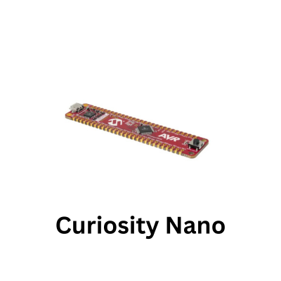
The Nano Explorer features an OLED display, this makes it an ideal first step to making projects. We can then take sensors for example, like the MCP9808 on the Nano Explorer board and display its values.
Using an OLED display with the PIC18F56Q71 Curiosity Nano provides a useful progression from basic GPIO experiments to communication with an external peripheral.
With the Curiosity Nano installed on the Curiosity Nano Explorer, the example demonstrates how firmware running on the PIC18F56Q71 can initialise and control the OLED through its communication interface.
The code is developed in Visual Studio Code, using the same embedded C workflow as the earlier LED example, but the project now introduces the additional configuration and data transfers required to communicate with a display controller.
Getting the OLED operating also establishes a useful foundation for later PIC18F56Q71 projects.
Once communication and basic display control have been verified, the same code can be extended to render alphanumeric characters, display ADC measurements, show sensor readings, present operating status or create a simple menu system.
OLED Example
This is what we will display in all its glory
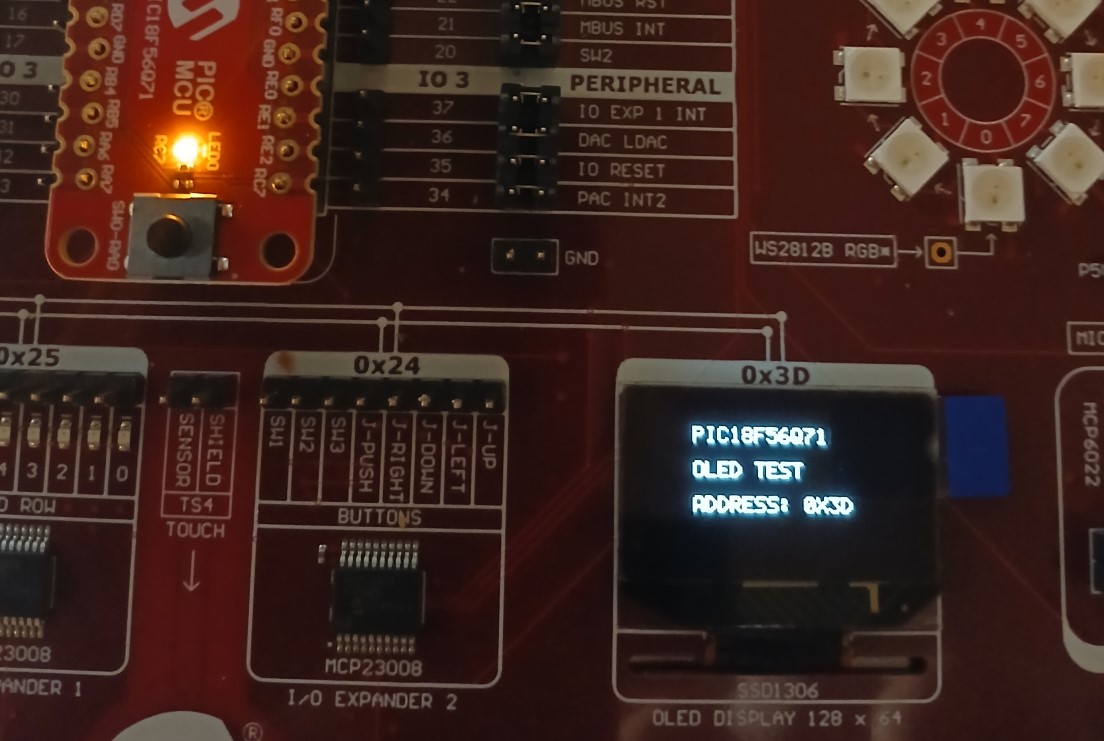
curiosity oled test
OLED code
This was in VS Code
Past it into main.c and
// Configuration Bits
#pragma config FEXTOSC = OFF
#pragma config RSTOSC  = HFINTOSC_1MHZ // Software switches to 16MHz
#pragma config CLKOUTEN = OFF
#pragma config CSWEN   = ON
#pragma config MCLRE   = EXTMCLR
#pragma config PWRTS   = PWRT_OFF
#pragma config WDTE    = OFF

#define _XTAL_FREQ 16000000
#include <xc.h>

#define SSD1306_I2C_ADDR 0x3D
#define HEARTBEAT_LED    LATCbits.LATC7

// Software I2C Pin Definitions on Explorer Socket (RC3 = SCL, RC4 = SDA)
#define SCL_PIN TRISCbits.TRISC3
#define SDA_PIN TRISCbits.TRISC4
#define SDA_IN  PORTCbits.RC4

// Font Table (ASCII 32 to 90)
const unsigned char FONT_5x7[][5] = {
    {0x00, 0x00, 0x00, 0x00, 0x00}, // ' '
    {0x00, 0x00, 0x5F, 0x00, 0x00}, // '!'
    {0x00, 0x07, 0x00, 0x07, 0x00}, // '"'
    {0x14, 0x7F, 0x14, 0x7F, 0x14}, // '#'
    {0x24, 0x2A, 0x7F, 0x2A, 0x12}, // '$'
    {0x23, 0x13, 0x08, 0x64, 0x62}, // '%'
    {0x36, 0x49, 0x55, 0x22, 0x50}, // '&'
    {0x00, 0x05, 0x03, 0x00, 0x00}, // '\''
    {0x00, 0x1C, 0x22, 0x41, 0x00}, // '('
    {0x00, 0x41, 0x22, 0x1C, 0x00}, // ')'
    {0x14, 0x08, 0x3E, 0x08, 0x14}, // '*'
    {0x08, 0x08, 0x3E, 0x08, 0x08}, // '+'
    {0x00, 0x50, 0x30, 0x00, 0x00}, // ','
    {0x08, 0x08, 0x08, 0x08, 0x08}, // '-'
    {0x00, 0x60, 0x60, 0x00, 0x00}, // '.'
    {0x20, 0x10, 0x08, 0x04, 0x02}, // '/'
    {0x3E, 0x51, 0x49, 0x45, 0x3E}, // '0'
    {0x00, 0x42, 0x7F, 0x40, 0x00}, // '1'
    {0x42, 0x61, 0x51, 0x49, 0x46}, // '2'
    {0x21, 0x41, 0x45, 0x4B, 0x31}, // '3'
    {0x18, 0x14, 0x12, 0x7F, 0x10}, // '4'
    {0x27, 0x45, 0x45, 0x45, 0x39}, // '5'
    {0x3C, 0x4A, 0x49, 0x49, 0x30}, // '6'
    {0x01, 0x71, 0x09, 0x05, 0x03}, // '7'
    {0x36, 0x49, 0x49, 0x49, 0x36}, // '8'
    {0x06, 0x49, 0x49, 0x29, 0x1E}, // '9'
    {0x00, 0x36, 0x36, 0x00, 0x00}, // ':'
    {0x00, 0x56, 0x36, 0x00, 0x00}, // ';'
    {0x08, 0x14, 0x22, 0x41, 0x00}, // '<'
    {0x14, 0x14, 0x14, 0x14, 0x14}, // '='
    {0x00, 0x41, 0x22, 0x14, 0x08}, // '>'
    {0x02, 0x01, 0x51, 0x09, 0x06}, // '?'
    {0x32, 0x49, 0x79, 0x41, 0x3E}, // '@'
    {0x7E, 0x11, 0x11, 0x11, 0x7E}, // 'A'
    {0x7F, 0x49, 0x49, 0x49, 0x36}, // 'B'
    {0x3E, 0x41, 0x41, 0x41, 0x22}, // 'C'
    {0x7F, 0x41, 0x41, 0x22, 0x1C}, // 'D'
    {0x7F, 0x49, 0x49, 0x49, 0x41}, // 'E'
    {0x7F, 0x09, 0x09, 0x09, 0x01}, // 'F'
    {0x3E, 0x41, 0x49, 0x49, 0x7A}, // 'G'
    {0x7F, 0x08, 0x08, 0x08, 0x7F}, // 'H'
    {0x00, 0x41, 0x7F, 0x41, 0x00}, // 'I'
    {0x20, 0x40, 0x41, 0x3F, 0x01}, // 'J'
    {0x7F, 0x08, 0x14, 0x22, 0x41}, // 'K'
    {0x7F, 0x40, 0x40, 0x40, 0x40}, // 'L'
    {0x7F, 0x02, 0x0C, 0x02, 0x7F}, // 'M'
    {0x7F, 0x04, 0x08, 0x10, 0x7F}, // 'N'
    {0x3E, 0x41, 0x41, 0x41, 0x3E}, // 'O'
    {0x7F, 0x09, 0x09, 0x09, 0x06}, // 'P'
    {0x3E, 0x41, 0x51, 0x21, 0x5E}, // 'Q'
    {0x7F, 0x09, 0x19, 0x29, 0x46}, // 'R'
    {0x46, 0x49, 0x49, 0x49, 0x31}, // 'S'
    {0x01, 0x01, 0x7F, 0x01, 0x01}, // 'T'
    {0x3F, 0x40, 0x40, 0x40, 0x3F}, // 'U'
    {0x1F, 0x20, 0x40, 0x20, 0x1F}, // 'V'
    {0x3F, 0x40, 0x38, 0x40, 0x3F}, // 'W'
    {0x63, 0x14, 0x08, 0x14, 0x63}, // 'X'
    {0x07, 0x08, 0x70, 0x08, 0x07}, // 'Y'
    {0x61, 0x51, 0x49, 0x45, 0x43}  // 'Z'
};

//  Software I2C Low-Level Operations
void I2C_Delay(void)
{
    __delay_us(4); // Timing delay for ~100kHz standard mode
}

void SW_I2C_Init(void)
{
    // Force 16 MHz HFINTOSC Internal Clock
    OSCCON1 = 0x60;
    OSCFRQ  = 0x05;
    while (!OSCCON3bits.ORDY);

    // Disable analog on RC3 and RC4
    ANSELCbits.ANSELC3 = 0;
    ANSELCbits.ANSELC4 = 0;

    // Set output latches LOW
    LATCbits.LATC3 = 0;
    LATCbits.LATC4 = 0;

    // Enable internal pull-ups
    WPUCbits.WPUC3 = 1;
    WPUCbits.WPUC4 = 1;

    // Release lines pulled HIGH
    SCL_PIN = 1;
    SDA_PIN = 1;
    I2C_Delay();
}

void SW_I2C_Start(void)
{
    SDA_PIN = 1; SCL_PIN = 1; I2C_Delay();
    SDA_PIN = 0; I2C_Delay(); // SDA goes LOW while SCL is HIGH
    SCL_PIN = 0; I2C_Delay();
}

void SW_I2C_Stop(void)
{
    SDA_PIN = 0; SCL_PIN = 0; I2C_Delay();
    SCL_PIN = 1; I2C_Delay();
    SDA_PIN = 1; I2C_Delay(); // SDA goes HIGH while SCL is HIGH
}

void SW_I2C_Write(unsigned char byte)
{
    for (unsigned char i = 0; i < 8; i++)
    {
        if ((byte >> (7 - i)) & 0x01)
        {
            SDA_PIN = 1; // High bit
        }
        else
        {
            SDA_PIN = 0; // Low bit
        }
        I2C_Delay();
        SCL_PIN = 1; I2C_Delay(); // Clock High
        SCL_PIN = 0; I2C_Delay(); // Clock Low
    }

    // Ignore ACK response to prevent locking up
    SDA_PIN = 1;
    I2C_Delay();
    SCL_PIN = 1; I2C_Delay();
    SCL_PIN = 0; I2C_Delay();
}

//  SSD1306 Display Engine
void SSD1306_Command(unsigned char cmd)
{
    SW_I2C_Start();
    SW_I2C_Write((SSD1306_I2C_ADDR << 1) | 0);
    SW_I2C_Write(0x00); // Command byte
    SW_I2C_Write(cmd);
    SW_I2C_Stop();
}

void SSD1306_Data(unsigned char data)
{
    SW_I2C_Start();
    SW_I2C_Write((SSD1306_I2C_ADDR << 1) | 0);
    SW_I2C_Write(0x40); // Data byte
    SW_I2C_Write(data);
    SW_I2C_Stop();
}

void SSD1306_Init(void)
{
    __delay_ms(100);

    SSD1306_Command(0xAE);
    SSD1306_Command(0xD5);
    SSD1306_Command(0x80);
    SSD1306_Command(0xA8);
    SSD1306_Command(0x3F);
    SSD1306_Command(0xD3);
    SSD1306_Command(0x00);
    SSD1306_Command(0x40);
    SSD1306_Command(0x8D);
    SSD1306_Command(0x14);
    SSD1306_Command(0x20);
    SSD1306_Command(0x00);
    SSD1306_Command(0xA1);
    SSD1306_Command(0xC8);
    SSD1306_Command(0xDA);
    SSD1306_Command(0x12);
    SSD1306_Command(0x81);
    SSD1306_Command(0xCF);
    SSD1306_Command(0xD9);
    SSD1306_Command(0xF1);
    SSD1306_Command(0xDB);
    SSD1306_Command(0x40);
    SSD1306_Command(0xA4);
    SSD1306_Command(0xA6);
    SSD1306_Command(0xAF);
}

void SSD1306_Clear(void)
{
    for (unsigned char page = 0; page < 8; page++)
    {
        SSD1306_Command(0xB0 + page);
        SSD1306_Command(0x00);
        SSD1306_Command(0x10);

        for (unsigned char col = 0; col < 128; col++)
        {
            SSD1306_Data(0x00);
        }
    }
}

void SSD1306_DrawChar(char c, unsigned char page, unsigned char col)
{
    if (c >= 'a' && c <= 'z') c -= 32;
    if (c < 32 || c > 90) c = ' ';

    unsigned char font_index = c - 32;

    SSD1306_Command(0xB0 + page);
    SSD1306_Command(0x00 + (col & 0x0F));
    SSD1306_Command(0x10 + ((col >> 4) & 0x0F));

    for (unsigned char i = 0; i < 5; i++)
    {
        SSD1306_Data(FONT_5x7[font_index][i]);
    }
    SSD1306_Data(0x00);
}

void SSD1306_DrawString(const char *str, unsigned char page, unsigned char col)
{
    while (*str && col < 122)
    {
        SSD1306_DrawChar(*str++, page, col);
        col += 6;
    }
}

int main(void)
{
    // Onboard Heartbeat LED0
    ANSELCbits.ANSELC7 = 0;
    TRISCbits.TRISC7   = 0;

    SW_I2C_Init();
    SSD1306_Init();
    SSD1306_Clear();

    SSD1306_DrawString("PIC18F56Q71", 1, 22);
    SSD1306_DrawString("OLED TEST", 3, 22);
    SSD1306_DrawString("ADDRESS: 0X3D", 5, 22);

    while (1)
    {
        HEARTBEAT_LED = !HEARTBEAT_LED; // Flash RC7
        __delay_ms(500);
    }

    return 0;
}
Verification
- Run MPLAB: Program Device.
- Heartbeat LED (RC7) will toggle every 0.5 seconds, proving the processor is not locked up waiting on hardware I2C flags.
- The display will render the text in SSD1306_DrawString on the display
