

In this article we look at the A look at a DsPIC30F4011 Development Board again. This time we will use the buttons on the development board and light the LEDs
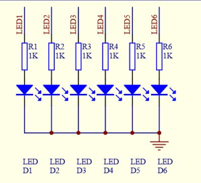
Lets look at the DsPic and the LED’s on the schematic. You can see that these are all connected to the RE port
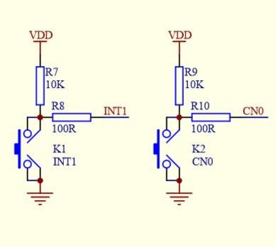
Now lets look at the buttons. You can see K1 is connected to RD0 and K2 is connected to RC14
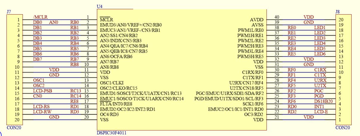
Now here is the pinout of the DsPic
Hardware
The board costs about $25
| Description | Link |
| DsPIC30F4011 Development Board | DsPIC 30F4011 Development Board/dsPIC Experimental Board/System Board/ |
Code
This is the main code example, the complete project will be posted below
[codesyntax lang=”cpp”]
/************************************************* ********************/
/*File description: key input experiment INT1 (RD0) key press RE LED flashes*/
/*Hardware configuration: MCU: dsPIC30F4011 development board, OSC: use off-chip 7.3728MHz X 16 PLL=117.9648MHz oscillator.*/
/*Software configuration: development environment MPLAB X IDE v5.10 compiler XC16 v1.50 */
/************************************************* *******************/
#include "p30f4011.h"

//Configuration bits
_FOSC(0Xc307); //FCKSM = 00; clock switch enable FOS = 0111 main oscillator XT crystal mode external 7.3728MHz
_FWDT(0X0000);
_FBORPOR(0X83A2);//MCLREN enable Undervoltage 2.7V Power-up delay 16MS
_FGS(0X03);

void Delay_1ms(unsigned int t)//t = 1000 about 1s
{
    unsigned int i,j;
    for(i = 0;i <t;i ++)
        for(j = 0;j <2000;j ++);
}

//Oscillator configuration
void System_Clock(void)
{
    //Generate Fosc = 7.3728MHz 117.9648MHz 30MIPS
    while (OSCCONbits.COSC!= 0b011)
    while (OSCCONbits.LOCK!= 1) {};//PLL is locked
}

void System_Init(void)
{
    PWMCON1 = 0x0000; //General IO
    TRISE = 0x0000; //Set output
    PORTE = 0xffff;//Set high
    TRISCbits.TRISC14 = 1; //RC13 port is set as input
    TRISDbits.TRISD0 = 1; //RC13 port is set as input
}

int main()
{
    System_Clock();
    System_Init();
    while(1)
    {
        if((PORTCbits.RC14 == 0)||(PORTDbits.RD0 == 0))
        {
            Delay_1ms(20);
            if((PORTCbits.RC14 == 0)||(PORTDbits.RD0 == 0))
            {
                while(!PORTCbits.RC14);//Wait for the key to be released
                while(!PORTDbits.RD0);//Wait for the key to be released
                PORTE = 0xffff;
                Delay_1ms(500);
            }
        }
        PORTE = 0x0000;
    }
}
[/codesyntax]
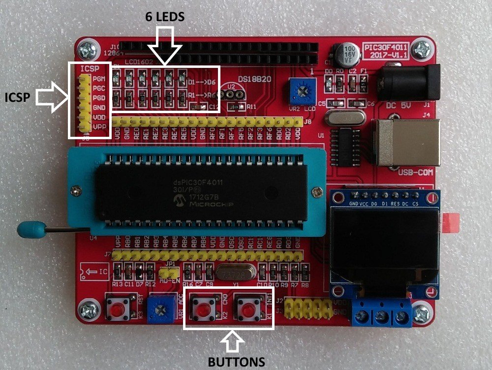
Upload this to your development board, I connected my Pickit4 to the ICSP connection – its a 1 to 1 connection. Once programming is completed press the buttons marked K1 and K2. The LEDs should all light when you release the button
You can see the ICSP and LEDs highlighted below on the development board
DsPIC30F4011 Development Board button example
Link
https://github.com/getelectronics/PICLearning/tree/master/DsPIC30F4011%20Development%20Board/2.KEY.X
