
The next in our list of arduino shields that we will be testing with the Chipkit Max32 is known as the Clock shield or Tick tock shield
Here is a picture of this shield
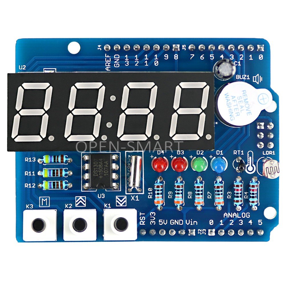
Features
Battery Holder : Battery on the card to the real-time clock chip power supply , making the board can continue to power down timer ;
Buzzer : 5V DC buzzer , do alarm clock, key tone ;
Photoresistor : intensity of ambient light sensor ;
Thermistor: detecting environmental temperature ;
K1 ~ K3: SCM can be scanned directly touch of a button ;
U5: TM1636, namely, four 8-segment common anode LED Driver IC ;
U3: DS1307, namely, real-time clock chip ;
D1 ~ D4: blue, green , red, red , 3mm plug LED.
Digital tube: 4 8 segments of positive points with a digital clock , and the decimal point is not displayed , only for identification purposes direction .
Occupied Arduino pin Resources:
Total occupied nine digital pins , two analog input pins, an I2C interface
D2: control blue LED1;
D3: Control the green LED2;
D4: Control the red LED3;
D5: Control the red LED4;
D7: connection TM1636 clock pin SCLK;
D8: TM1636 data connection pin DIO;
D9: control keys K1;
D10: control buttons K2;
D11: control buttons K3;
A0: poll readings from temperature sensor;
A1: poll readings from light sensor;
A4: connect the DS1307 I2C data pin SDA;
A5: connect the DS1307 I2C clock pin SCL
Code Examples
Flash LED
[codesyntax lang=”cpp”]
int led1 = 2;

// the setup routine runs once when you press reset:
void setup()
{
  // initialize the digital pin as an output.
  pinMode(led1, OUTPUT);
}

// the loop routine runs over and over again forever:
void loop() {
  digitalWrite(led1, HIGH);   // turn the LED on (HIGH is the voltage level)
  delay(1000);               // wait for a second
  digitalWrite(led1, LOW);    // turn the LED off by making the voltage LOW
  delay(1000);               // wait for a second
}
[/codesyntax]
Knightrider LED effect
[codesyntax lang=”cpp”]
int pinArray[] = {2, 3, 4, 5};
int count = 0;
int timer = 100;

void setup()
{
  for (count=0;count<4;count++)
  {
    pinMode(pinArray[count], OUTPUT);
  }
}

void loop()
{
  for (count=0;count<4;count++)
  {
   digitalWrite(pinArray[count], HIGH);
   delay(timer);
   digitalWrite(pinArray[count], LOW);
   delay(timer);
  }
  for (count=3;count>=0;count--)
  {
   digitalWrite(pinArray[count], HIGH);
   delay(timer);
   digitalWrite(pinArray[count], LOW);
   delay(timer);
  }
}
[/codesyntax]
LDR example
Link
You can pick up one of these shields for under $7
