
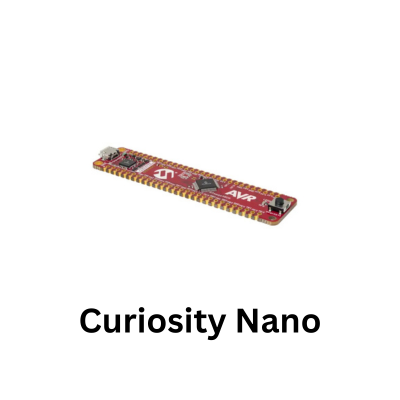
The PIC18F56Q71 Curiosity Nano has a good old LED on it so lets do the usual basic example.
With the development environment already configured in Visual Studio Code, the example concentrates on the small amount of firmware required to configure the LED GPIO as an output and repeatedly change its state.
Although the visible result is simple, it confirms that the project builds correctly, the PIC18F56Q71 can be programmed successfully and the application is manipulating the expected hardware output.
The example also provides an introduction to the PIC18F56Q71 GPIO register model before moving on to timers, interrupts and other peripherals.
Configuring a digital output requires more than simply assigning a value to a pin: the appropriate direction and output-latch settings must be understood, along with any relevant analog configuration.
The same principles used to blink an LED apply later when GPIO pins control status indicators, peripheral enable signals, chip-select lines and external circuitry.
Once the basic blink example is working, it also provides a convenient reference project for replacing the software delay with a hardware timer or timer interrupt.
Update .vscode/c_cpp_properties.json for PIC18F56Q71
Update your workspace configuration to point to the PIC18F-Q_DFP header files:
These are my locations
{
  "configurations": [
    {
      "name": "PIC18F56Q71",
      "includePath": [
        "${workspaceFolder}/**",
        "C:/Users/user/.mchp_packs/Microchip/PIC18F-Q_DFP/1.25.433/xc8/pic/include/**",
        "C:/Program Files/Microchip/xc8/v3.10/pic/include/**"
      ],
      "defines": [
        "_18F56Q71",
        "__18F56Q71",
        "__XC8"
      ],
      "forcedInclude": [
        "C:/Users/user/.mchp_packs/Microchip/PIC18F-Q_DFP/1.25.433/xc8/pic/include/proc/pic18f56q71.h"
      ],
      "compilerPath": "C:/Program Files/Microchip/xc8/v3.10/bin/xc8-cc.exe",
      "cStandard": "c11",
      "intelliSenseMode": "windows-gcc-x64"
    }
  ],
  "version": 4
}
- Verify your pack path under C:\Users\user\.mchp_packs\Microchip\PIC18F-Q_DFP\ and update the folder name/username/version number if needed).
- Verify the PIC include file, especially the version under C:/Program Files/Microchip/xc8/v3.10/pic/include/
- Verify the compiler path especially the version under C:/Program Files/Microchip/xc8/v3.10/bin/xc8-cc.exe
When mounted in the Explorer socket, the PIC18F56Q71 maps its onboard yellow User LED0 to PF3 (Active Low).
Minimal LED Blink Code (64 MHz Clock)
The PIC18F56Q71 features an internal oscillator capable of running up to 64 MHz out of the box.
Replace main.c with this code:
// Configuration Bits for PIC18F56Q71
#pragma config FEXTOSC = OFF          // External Oscillator Selection (Disabled)
#pragma config RSTOSC  = HFINTOSC_1MHZ// Start safely at 1MHz HFINTOSC
#pragma config CLKOUTEN = OFF         // Clock Out Enable
#pragma config PR1WAY  = OFF          // PRLOCKED bit can be cleared/set repeatedly
#pragma config CSWEN   = ON           // Clock Switch Enable
#pragma config FCMEN   = OFF          // Fail-Safe Clock Monitor Enable

#pragma config MCLRE   = EXTMCLR      // MCLR Pin Enable
#pragma config PWRTS   = PWRT_OFF     // Power-up Timer Enable
#pragma config MVECEN  = OFF          // Interrupt Vectors disabled
#pragma config WDTE    = OFF          // Watchdog Timer Disabled

#define _XTAL_FREQ 1000000            // 1 MHz CPU Frequency matching reset state
#include <xc.h>

// LED0 on PIC18F56Q71 Curiosity Nano is wired to RC7
#define LED0_PIN LATCbits.LATC7

int main(void)
{
    // RC7 as Digital Output
    ANSELCbits.ANSELC7 = 0; // Digital I/O
    TRISCbits.TRISC7   = 0; // Output

    // RC2 (LED0) as a secondary backup pin
    ANSELCbits.ANSELC2 = 0;
    TRISCbits.TRISC2   = 0;

    while (1)
    {
        // Active-Low: 0 = ON, 1 = OFF
        LED0_PIN = 0;
        LATCbits.LATC2 = 1; // Active-High for baseboard LED
        __delay_ms(500);

        LED0_PIN = 1;
        LATCbits.LATC2 = 0;
        __delay_ms(500);
    }

    return 0;
}
Build and Program
- Open the Command Palette (Ctrl + Shift + P).
- Run MPLAB: Select Device \rightarrow choose PIC18F56Q71.
- Run MPLAB: Select Tool \rightarrow choose Curiosity Nano.
- Run MPLAB: Program Device.
Once flashed, LED0 (PF3) on the PIC18F56Q71 module will blink steadily every 0.5 seconds. You can adjust that time if you want by modifying the value in __delay_ms(500).
That’s us started, onwards to more exciting projects and examples.
