
3.6K
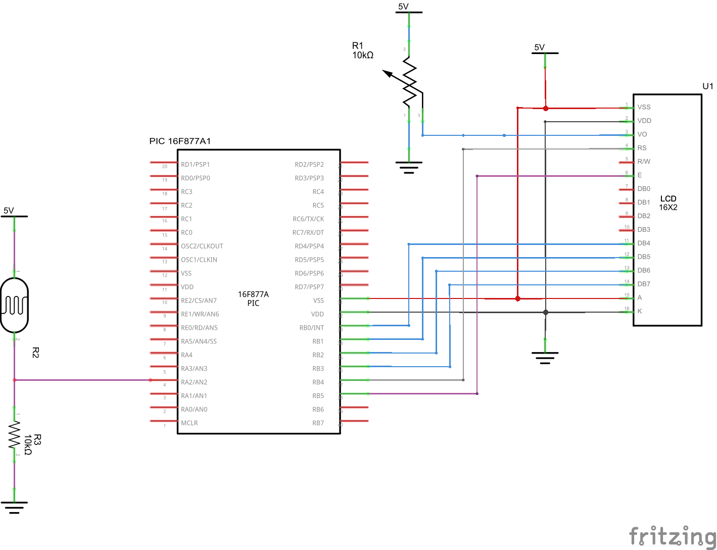
In this example we connect an LDR to ADC channel 2 which is PA 2. Once again you will get a value in theory between 0 and 1023. The more light that there is the higher the value.
We will read the value in from the LDR and display this on the LCD
Schematic
PIC16F877 LDR
Code
The example was written using mikroC pro evaluation version
[codesyntax lang=”c”]
sbit LCD_RS at RB4_bit;
sbit LCD_EN at RB5_bit;
sbit LCD_D4 at RB0_bit;
sbit LCD_D5 at RB1_bit;
sbit LCD_D6 at RB2_bit;
sbit LCD_D7 at RB3_bit;

sbit LCD_RS_Direction at TRISB4_bit;
sbit LCD_EN_Direction at TRISB5_bit;
sbit LCD_D4_Direction at TRISB0_bit;
sbit LCD_D5_Direction at TRISB1_bit;
sbit LCD_D6_Direction at TRISB2_bit;
sbit LCD_D7_Direction at TRISB3_bit;
unsigned int adcvalue,value,temp_res;
unsigned char car,x,y;
char *voltage = "00.00";
long temp;

// Routine to show the value of the ADC_read
void ShowADC(int x, int y, unsigned int adcvalue)
{
car = adcvalue / 1000;
LCD_Chr(x,y,48+car);
adcvalue=adcvalue-1000*car;
car = (adcvalue / 100);
LCD_Chr_CP(48+car);
adcvalue=adcvalue-100*car;
car = (adcvalue / 10);
LCD_Chr_CP(48+car);
adcvalue=adcvalue-10*car;
car = adcvalue;
LCD_Chr_CP(48+car);
delay_ms(30);
}

void main()
{
TRISA = 0xFF; // PORTA is input
TRISB = 0;
PORTB = 0;
Lcd_Init(); // Initialize LCD
Lcd_Cmd(_LCD_CLEAR); // Clear display
Lcd_Cmd(_LCD_CURSOR_OFF); // Cursor off
Lcd_Out(1, 1, " ADC :");
do {
temp_res = ADC_Read(2); // Get 10-bit results of AD conversion
adcvalue = temp_res;
ShowADC (1,7,adcvalue);
Delay_ms(300);

} while(1);

} // end main
[/codesyntax]
Links
Microcontroller Programmer Kit Development Board for PIC microcontroller evaluation QL200 PIC
50 pcs Light Dependent Resistors
