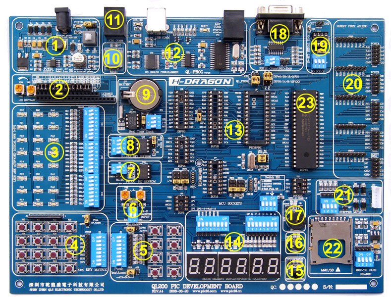
Timers are crucial in PIC microcontroller programming for delay generation, frequency measurement, and periodic event triggering. However, because timers are limited in size (8-bit, 16-bit), they overflow when they exceed their maximum value.
Handling timer overflows correctly is essential to ensure accurate timing and event scheduling.
This tutorial covers:
- Understanding Timer Overflow
- Configuring Timer0 for Overflow Interrupts
- Handling Timer1 Overflow (16-bit Timer)
- Calculating Timer Overflow Period
- Using Timer Interrupt Service Routines (ISRs)
- Practical Examples in Embedded C (MPLAB XC8)
Understanding Timer Overflow in PIC
Timers in PIC microcontrollers increment every instruction cycle and overflow when reaching their maximum value.
Timer Overflow Behavior
| Timer Type | Bit-Size | Max Value | Overflow After |
|---|---|---|---|
| Timer0 | 8-bit | 255 | Overflows at 256 counts |
| Timer1 | 16-bit | 65,535 | Overflows at 65,536 counts |
| Timer2 | 8-bit | 255 | Overflows at 256 counts (used for PWM) |
Timer Overflow Calculation
The time taken for an overflow is:
Toverflow=(MaxTimerValue+1−InitialValue)×PrescalerFosc/4T_{overflow} = \frac{(Max Timer Value + 1 – Initial Value) \times Prescaler}{F_{osc}/4}
Where:
- Max Timer Value = 255 for Timer0, 65535 for Timer1
- Initial Value = Preloaded Timer Value
- Prescaler = Divides the timer clock
- Fosc = Oscillator Frequency
Example:
For PIC16F877A, Timer0 with 8MHz crystal and a prescaler of 256, the overflow time is:
Toverflow=(256)×2568MHz/4=32.768msT_{overflow} = \frac{(256) \times 256}{8MHz/4} = 32.768ms
This means Timer0 overflows every 32.768ms.
Configuring Timer0 Overflow Interrupt (8-bit Timer)
Timer0 is an 8-bit timer, meaning it overflows after 256 counts.
Steps to Configure Timer0 for Overflow
- Set up Timer0 (TMR0).
- Enable Timer0 interrupt.
- Write an ISR to handle overflow events.
Example: Using Timer0 Overflow to Blink LED Every Second
#include <xc.h>

// CONFIGURATION BITS
#pragma config FOSC = XT, WDTE = OFF, PWRTE = OFF, BOREN = ON, LVP = OFF

#define _XTAL_FREQ 8000000  // Define CPU frequency (8MHz)
#define TIMER_PRELOAD 60     // Preload for 1s delay

void __interrupt() timer0_isr(void) {
    if (T0IF) {  // Check if Timer0 overflowed
        TMR0 = TIMER_PRELOAD;  // Reload timer
        T0IF = 0;  // Clear overflow flag
        PORTB ^= (1 << 0);  // Toggle LED on RB0
    }
}

void timer0_init() {
    OPTION_REG = 0x07;  // Prescaler 1:256
    TMR0 = TIMER_PRELOAD;  // Load initial value
    T0IE = 1;  // Enable Timer0 interrupt
    GIE = 1;   // Enable global interrupts
}

void main() {
    TRISB0 = 0;  // Set RB0 as output
    timer0_init();  // Initialize Timer0

    while (1) {
        // Main loop does nothing, Timer ISR handles LED blinking
    }
}
How It Works
- Timer0 overflows every 32.768ms.
- Interrupt Service Routine (ISR) reloads the timer and toggles the LED.
Handling Timer1 Overflow (16-bit Timer)
Timer1 is 16-bit, allowing a wider range of timing delays.
Example: Using Timer1 Overflow for 1-Second Delay
#include <xc.h>

// CONFIGURATION BITS
#pragma config FOSC = XT, WDTE = OFF, PWRTE = OFF, BOREN = ON, LVP = OFF

#define _XTAL_FREQ 8000000  // 8MHz Oscillator
#define TIMER1_PRELOAD 3036  // Preload for 1-second delay

void __interrupt() timer1_isr(void) {
    if (TMR1IF) {  // Check Timer1 overflow
        TMR1 = TIMER1_PRELOAD;  // Reload Timer1
        TMR1IF = 0;  // Clear overflow flag
        PORTB ^= (1 << 0);  // Toggle LED
    }
}

void timer1_init() {
    T1CON = 0x31;  // Enable Timer1, prescaler 1:8
    TMR1 = TIMER1_PRELOAD;  // Preload Timer1
    TMR1IE = 1;  // Enable Timer1 overflow interrupt
    GIE = 1;  // Enable global interrupts
}

void main() {
    TRISB0 = 0;  // Set RB0 as output
    timer1_init();  // Initialize Timer1

    while (1);
}
How It Works
- Timer1 counts up to 65535.
- It overflows every second, toggling the LED.
Reloading Timer to Adjust Overflow Time
Since timers count continuously, we can preload the timer register to reduce overflow time.
Example: Adjusting Timer0 for 10ms Overflow
TMR0=256−10ms×8MHz4×256TMR0 = 256 – \frac{10ms \times 8MHz}{4 \times 256}
Setting TMR0 = 60 ensures 10ms timer overflow.
#define TIMER0_PRELOAD 60

void __interrupt() timer0_isr(void) {
    if (T0IF) {
        TMR0 = TIMER0_PRELOAD;  // Reload Timer0
        T0IF = 0;
    }
}
Practical Applications of Timer Overflow Handling
- Generating Delays Without Blocking Code
- Using ISR-based timers allows continuous execution without using __delay_ms().
- Measuring Time Intervals
- Use Timer1 overflow to measure event duration.
- Creating Real-Time Clock (RTC) Features
- Timer overflow can be used for seconds, minutes, and hours counting.
Best Practices
Always reload timer in ISR to prevent timing drift.
Use prescalers to extend overflow time and reduce CPU usage.
Keep ISRs short to avoid missing other interrupts.
Disable interrupts when modifying timer registers to avoid glitches.
Test with simulation tools like MPLAB X and Proteus.
Summary Table
| Timer | Size | Max Value | Common Uses |
|---|---|---|---|
| Timer0 | 8-bit | 255 | Short delays, LED blinking |
| Timer1 | 16-bit | 65535 | Long delays, frequency measurement |
| Timer2 | 8-bit | 255 | PWM generation |
Handling timer overflows is essential for accurate timing and event scheduling in PIC microcontrollers.
By correctly configuring Timer0 and Timer1, and using interrupts, you can achieve precise time delays without blocking the main code.


