
In this example we interface an AD keypad to our PIC16F877 and we also connect an LCD display. The LCD display is simply as a debug tool to display A/D readings, the nature of an AD keypad is that there are multiple puch buttons and these are all attached via one input, depending on which button is pressed a different value is read. So to test this out you would press each button individually and take a note of the values, then in your code you could perform actions based on these values. An example would be using a switch case statement in the code.
This example simply shows a method of displaying the A/D value on the LCD
Schematics and images
Here is the keypad we used, it takes 5v and GND and has an AD output, in our example we connect this to PORTA 0
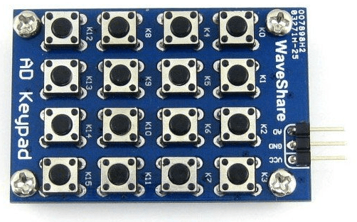
AD-Keypad
Here is the schematic of the AD keypad which shows in more detail how this works. As you can see if you press Key0 then the AD output will be directly to 0v, so the ADC value will be 0 as well but if you press Key15 then there are numerous resistors which alter the ADC value, on my system I got a reading of 960 (about 4.69 v)
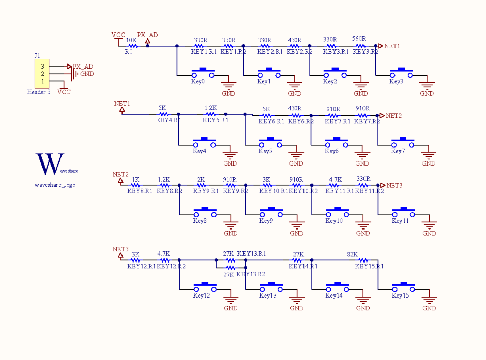
AD Keypad_SCH
The LCD was connected to PORTB, you can see in the code below the connections required
sbit LCD_RS at RB0_bit;
sbit LCD_EN at RB1_bit;
sbit LCD_D4 at RB2_bit;
sbit LCD_D5 at RB3_bit;
sbit LCD_D6 at RB4_bit;
sbit LCD_D7 at RB5_bit;
Code
code was written in mikroC
[codesyntax lang=”c”]
sbit LCD_RS at RB0_bit;
sbit LCD_EN at RB1_bit;
sbit LCD_D4 at RB2_bit;
sbit LCD_D5 at RB3_bit;
sbit LCD_D6 at RB4_bit;
sbit LCD_D7 at RB5_bit;

sbit LCD_RS_Direction at TRISB0_bit;
sbit LCD_EN_Direction at TRISB1_bit;
sbit LCD_D4_Direction at TRISB2_bit;
sbit LCD_D5_Direction at TRISB3_bit;
sbit LCD_D6_Direction at TRISB4_bit;
sbit LCD_D7_Direction at TRISB5_bit;


unsigned int adcvalue,value,temp_res;
unsigned char car,x,y;
char *voltage = "00.00";
long temp;

// Routine to show the value of the ADC_read
void ShowADC(int x, int y, unsigned int adcvalue)
{
car = adcvalue / 1000;
LCD_Chr(x,y,48+car);
adcvalue=adcvalue-1000*car;
car = (adcvalue / 100);
LCD_Chr_CP(48+car);
adcvalue=adcvalue-100*car;
car = (adcvalue / 10);
LCD_Chr_CP(48+car);
adcvalue=adcvalue-10*car;
car = adcvalue;
LCD_Chr_CP(48+car);
delay_ms(30);
}

// Routine to show the ADC_read conversion in Volts
void ShowVoltage (int x,int y, unsigned int value)
{
temp = (long)value* 5000;
temp = temp / 1023;
voltage[0] = temp/10000 + 48;
voltage[1] = (temp/1000)%10 + 48;
voltage[3] = (temp/100)%10 + 48;
voltage[4] = (temp/10)%10 + 48;
Lcd_Out (x,y,voltage);
delay_ms(30);
}

void main()
{

TRISB = 0x00;

Lcd_Init(); // Initialize LCD
Lcd_Cmd(_LCD_CLEAR); // Clear display
Lcd_Cmd(_LCD_CURSOR_OFF); // Cursor off
Lcd_Out(1, 1, " ADC :");
Lcd_Out(2, 1, " Voltage :");
do {
temp_res = ADC_Read(0); // Get 10-bit results of AD conversion
adcvalue = temp_res;
ShowADC (1,7,adcvalue);
ShowVoltage(2,11,adcvalue);
Delay_ms(300);

} while(1);

} // end main
[/codesyntax]
Links
AD Keypad 16 4×4 Accessory board matrix buttons controlled ADC AD port keyboard
