
2.2K
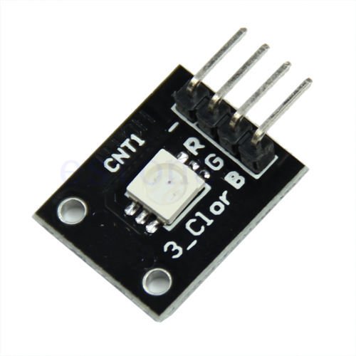
In this example we used an RGB LED breakout board, here is a picture of an Surface mount RGB breakout board which was similar to the one we used, the PIC was a PIC16F877
RGB Module
We will connect the Red, Green and blue connections up to the following port pins C0, C1 and C2
Then we will send the respective pin high (1) and switch the selected colour on.
Code
This was written in mikroC PRO for PIC
[codesyntax lang=”c”]
void main()
{
TRISC = 0x00; // Sets all pins in PORTC as output
PORTC = 0xFF;


while(1)
{

PORTC = 0xFF;
delay_ms(500);
PORTC = 0xFE; //red
delay_ms(500);
PORTC = 0xFD; //green
delay_ms(500);
PORTC = 0xFB; //blue
delay_ms(500);

}
}
[/codesyntax]
