In this example we connect a MAx7219 8×8 LED matrix to our PIC 16F819 development board
Here is a picture of the module, these are very common and available from many sites
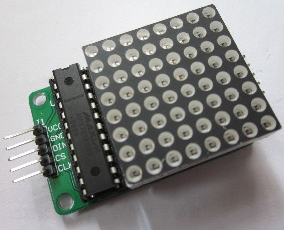
The connections are as follows
| MAX7219 Pin | Pic16F819 Pin |
| CS | 17 |
| DIN | 18 |
| CLK | 1 |
Code
The following code was written using the MikroC pro for PIC compiler
[codesyntax lang=”cpp”]
#define CS_Pin PORTA.F2
#define DIN_Pin PORTA.F1
#define CLK_Pin PORTA.F0

unsigned const short Alphabet[156]={
0x7f, 0x88, 0x88, 0x88, 0x88, 0x7f, // A
0x6e, 0x91, 0x91, 0x91, 0x91, 0xff, // B
0x42, 0x81, 0x81, 0x81, 0x81, 0x7E, // C
0x7e, 0x81, 0x81, 0x81, 0x81, 0xff, // D
0x91, 0x91, 0x91, 0x91, 0xff, 0x81, // E
0x80, 0x90, 0x90, 0x91, 0xff, 0x81, // F
0x4e, 0x89, 0x89, 0x81, 0x81, 0x7e, // G
0xff, 0x10, 0x10, 0x10, 0x10, 0xff, // H
0x00, 0x81, 0xff, 0xff, 0x81, 0x00, // I
0x00, 0x80, 0xfe, 0x81, 0x01, 0x06, // J
0x81, 0xc3, 0x24, 0x99, 0xff, 0x81, // K
0x03, 0x01, 0x01, 0x81, 0xff, 0x81, // L
0xff, 0x60, 0x18, 0x18, 0x60, 0xff, // M
0xff, 0x06, 0x08, 0x10, 0x60, 0xff, // N
0x7e, 0x81, 0x81, 0x81, 0x81, 0x7e, // O
0x70, 0x88, 0x88, 0x89, 0xff, 0x81, // P
0x7e, 0x87, 0x89, 0x85, 0x81, 0x7e, // Q
0x61, 0x93, 0x94, 0x98, 0x98, 0xff, // R
0x4e, 0x91, 0x91, 0x91, 0x91, 0x62, // S
0xc0, 0x81, 0xff, 0xff, 0x81, 0xc0, // T
0xfe, 0x01, 0x01, 0x01, 0x01, 0xfe, // U
0xfc, 0x02, 0x01, 0x01, 0x02, 0xfc, // V
0xff, 0x02, 0x04, 0x04, 0x02, 0xff, // W
0xc3, 0x24, 0x18, 0x18, 0x24, 0xc3, // X
0xc0, 0x20, 0x1f, 0x1f, 0x20, 0xc0, // Y
0xc3, 0xa1, 0x91, 0x89, 0x85, 0xc3, // Z
};

void SPI_Write_Byte(unsigned short num)
{
unsigned short t, Mask, Flag;
CLK_Pin = 0;
Mask = 128;
for (t=0; t<8; t++) { Flag = num & Mask; if(Flag == 0) { DIN_Pin = 0; } else { DIN_Pin = 1; } CLK_Pin = 1; CLK_Pin = 0; Mask = Mask >> 1;
}
}

void MAX7219_INIT() {

// Set BCD decode mode
CS_Pin = 0; // CS pin is pulled LOW
SPI_Write_Byte(0x09); // Select Decode Mode register
SPI_Write_Byte(0x00); // Select BCD mode for digits DIG0-DIG7
CS_Pin = 1; // CS pin is pulled HIGH

// Set display brighness
CS_Pin = 0; // CS pin is pulled LOW
SPI_Write_Byte(0x0A); // Select Intensity register
SPI_Write_Byte(0x05); // Set brightness
CS_Pin = 1; // CS pin is pulled HIGH

// Set display refresh
CS_Pin = 0; // CS pin is pulled LOW
SPI_Write_Byte(0x0B); // Select Scan-Limit register
SPI_Write_Byte(0x07); // Select digits DIG0-DIG3
CS_Pin = 1; // CS pin is pulled HIGH

// Turn on the display
CS_Pin = 0; // CS pin is pulled LOW
SPI_Write_Byte(0x0C);
SPI_Write_Byte(0x01);
CS_Pin = 1; // CS pin is pulled HIGH

// Disable Display-Test
CS_Pin = 0; // CS pin is pulled LOW
SPI_Write_Byte(0x0F); // Select Display-Test register
SPI_Write_Byte(0x00); // Disable Display-Test
CS_Pin = 1; // CS pin is pulled HIGH

}

void Write_Byte(unsigned short myColumn, unsigned short myValue)
{
CS_Pin = 0; // select max7219.
SPI_Write_Byte(myColumn); // send myColumn value to max7219 (digit place).
SPI_Write_Byte(myValue); // send myValue value to max7219 (digit place).
CS_Pin = 1; // deselect max7219.
}

// This is clear matrix function.
void Clear_Matrix(void)
{
unsigned short x;

for(x=1;x<9;x++)
{
Write_Byte(x,0x00);
}
}

void Write_Char(char myChar)
{
unsigned short Column, Start_Byte;

// Clear the display first.
Clear_Matrix();
// The next line defines our byte, from which to start the array.
Start_Byte = (myChar - 65) * 6; // 65 represents the letter "A" in ASCII code.
// We are using only columns from 2 through 7 for displaying the character.
for(Column=2;Column<8;Column++)
{
Write_Byte(Column, Alphabet[Start_Byte++]);
}
}

void main()
{
unsigned int x;
PORTA=0;
TRISA=0;

MAX7219_INIT(); // initialize max7219
do{
for(x=65;x<=90;x++) // Increment with 1, from 65 until 90.
{
Write_Char(x);
Delay_ms(1000); // This is our delay, between two consecutive character.
}
}while(1);
}
[/codesyntax]
Links
A nice low cost part for you collection, you can pick up the modules for under $2
MAX7219 dot matrix module