This is an example that shows how to use UART module of PIC16F877 microcontroller using mikroC compiler. In this case we use the mikroC Pro for PIC UART library.
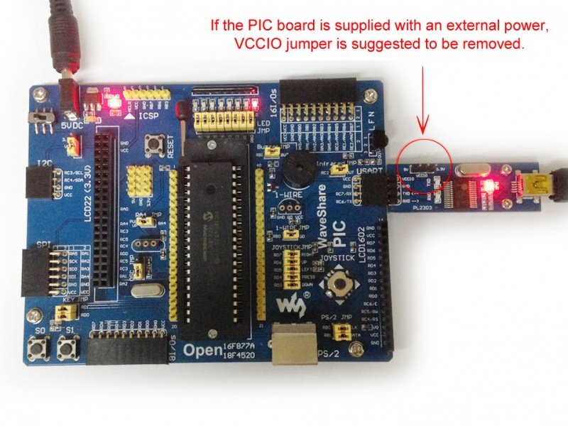
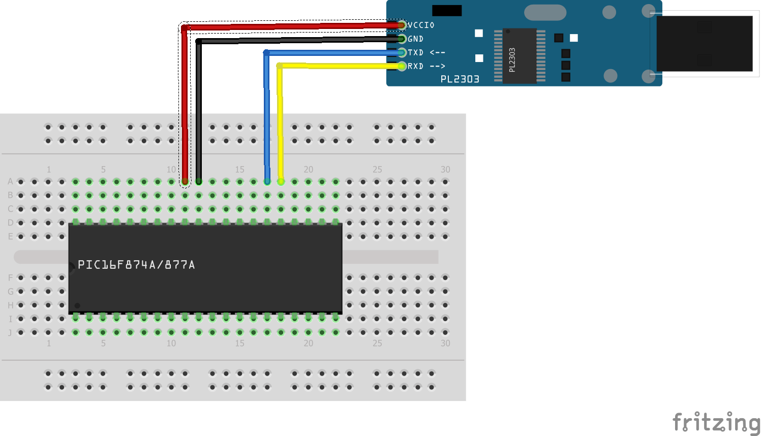
Pins RC6 and RC7 are used for the UART (serial) communication between the microcontroller and the computer. I decided to use a Pl2303 USB-Serial adaptor as this was part of a PIC kit that I use that was developed by Waveshare
Layout
In this example we only show the PIC16F877 and the PL2303 module, no external circuitry we are basically trying to show the simple connection above
Code
The code was written in mikroC Pro for Pic
[codesyntax lang=”cpp”]
 char i ;

 void main()
 {
   UART1_Init(19200); // Initialize USART module
    // (8 bit, 19200 baud rate, no parity bit...)
   delay_ms(2000);
   UART1_Write_Text("Hello world!");
   UART1_Write(13);      // Start a new line
   UART1_Write(10);
   UART1_Write_Text("PIC16F877A UART example");
   UART1_Write(13);     // Start a new line
   UART1_Write(10);
   while (1)
   {
     if (UART1_Data_Ready())
     { // If data has been received
      i = UART1_Read();     // read it
      UART1_Write(i);       // and send it back
     }
   }
 }
[/codesyntax]
Testing
Connect the pin side of a PL2303 USB UART Board (mini) to USART interface and the USB side to a PC.
Power up teh board and upload the hex file from the code above, i used the Pickit3 programmer to power the board
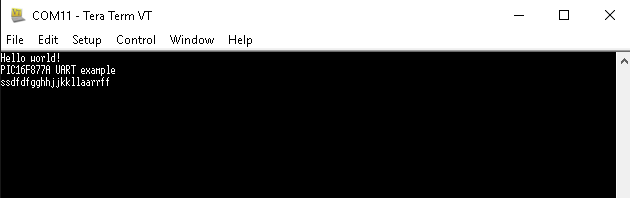
Run a terminal program , a couple of options are Putty or TeraTerm). Choose the corresponding COM port and set baud rate to 19200.
This is what you see this is TeraTerm
Links